The Core-PP kinematics architecture was engineered specifically for Poly Plotter (also documented as Max-A3), an automated multi-tool plotting machine developed in collaboration with Fablab Kerala.
The designation PP stands for Poly Plotter, while Core denotes its conceptual heritage derived from standard CoreXY motion systems.
The Design Challenge: Tool Pickup Clearance
The primary design driver was a unique mechanical constraint: the machine needed an automated tool changer that docks and picks up pen/tool cartridges directly from the left side of the chassis.
In a conventional CoreXY mechanism, continuous crossing belt runs traverse the outer perimeter of the gantry frame. When attempting to pick up a tool from the side edge, these belt loops inevitably collide and interfere with the tool-docking carriage and gantry clearance zone.
Why not standard CoreXY?
Under standard circumstances without peripheral side-docking requirements, standard CoreXY is the preferred choice. Core-PP was developed specifically to solve this physical obstruction by routing belt loops across separate physical elevations.
Dual-Plane Belt Routing Solution
To resolve the interference, Core-PP introduces two isolated belt loops separated across two distinct vertical planes:
- Motor A Loop (Red): Governs the direct horizontal displacement along the X-axis across the lower plane.
- Motor B Loop (Blue): Traverses an elevated plane to drive the differential Y-axis motion without crossing the left-hand tool-docking corridor.
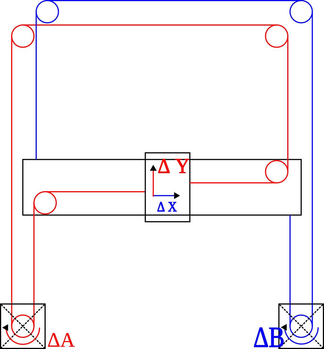
Core-PP belt routing layout: Motor A (ΔA, Red loop) and Motor B (ΔB, Blue loop) driving carriage toolhead (ΔX, ΔY)
Kinematic Transformation Equations
Forward Kinematics (Motor steps to Cartesian displacement)
ΔX = −ΔA
ΔY =
1
2
(ΔB − ΔA)
Inverse Kinematics (Cartesian targets to Motor commands)
ΔA = −
ΔX
|
ΔB = 2
ΔY −
ΔX
Motion Characteristics
Notice the unique property of the transformation matrix: unlike standard CoreXY where pure X or Y motion requires simultaneous dual-motor actuation at identical rates, in Core-PP:
- Pure X-axis travel is driven exclusively by Motor A (ΔX = −ΔA).
- Pure Y-axis travel requires coordinated differential action between both motors (ΔB = 2ΔY + ΔA).
- Stationary dual-motor mounting preserves low moving carriage inertia, enabling high acceleration across the drawing area.